Type of course:
Digital learning, Lesson
Language:
EN
Proficiency:
Intermediate
Target:
Professionals, Workers
The Data Link Layer (DLL) is responsible for forming the frames, addressing and basic error detection mechanism. Ethernet is used in a connection-less manner to simplify the transfer at DLL as much as possible. Further mechanisms ensuring the transfer robustness and reliability are usually left to upper-level protocols in the hierarchy.
Connectionless operation (used by Ethernet)
- best-effort service
- no guarantees are made
- each frame is handled independently of all others
- no error recovery mechanisms are invoked
- error detection prevents corrupted frames from being delivered to the higher-layer client
- efficient for channels with low error rate
- higher-layer mechanisms to recover from errors are needed
Connection-oriented operation (used by other protocols from the 802 family, not Ethernet)
- error and flow control
- the communicating partners must maintain state information
- connection establishment mechanism necessary
- additional overhead and complexity
- resource management is needed
Ethernet Frame Structure and Addressing
The Ethernet frame is structured as depicted in Figure 1 below:
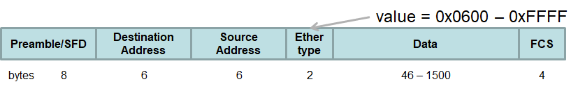
- Preamble
- 7 bytes of 0x55, SFD – 1 byte of 0xD5, i.e. 62 bits of ones and zeroes followed by 2 ones. This is important for the synchronization of the receiver
- Destination (DA) and source address (SA) – see Figure 2 below
- 48 bit address of the receiver/sender
- The first bit of the destination address is called I/G bit (individual/group) … I/G=0 for unicast, I/G=1 for multicast. Multicast destination addresses are destined for a group of recipients.
- Source address is always unicast. The first bit of the source address is always 0 for Ethernet.
- The addresses can be locally or globally administered, i.e. the network administrator can assign locally administered addresses and is responsible for their uniqueness within the network.
- Organizationally unique identifier (OUI) is assigned by IEEE to organisations who produce network interfaces. It is their responsibility to ensure that the MAC addresses are unique within the assigned OUI address space. If an organisation runs out of addresses within the OUI address space it can ask for another OUI.
- Frame Check Sequence (FCS)
- checksum from DA through the end of the data field, 32-bit cyclic redundancy check (CRC)
- Type (EtherType)
- identifies the above-running client protocol. It allows Ethernet multiplexing upward among higher-layer protocols, such as IP, Profinet, etc. In such a way, the attached process can be determined to deal with the data delivered with the Ethernet frame.
- The Type field values are maintained by the IEEE and are in the range of 0x0600 – 0xFFFF. Originally, the assignments were made by Xerox Corporation.
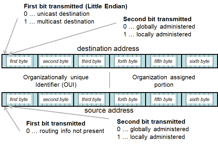
The ordering is big endian for the octet order (leftmost octet is sent first) and little endian for bit order (rightmost bit, i.e. LSB, is sent first).
The following list shows some Organization Unique Identifiers (OUIs) you can encounter in industrial communication systems based on Ethernet. In all these OUIs, the I/G bit, i.e. the multicast bit, is 0.
- Siemens AG … 40-EC-F8, 08-00-06, 00-23-41
- WAGO … 68-23-4B, 00-30-DE, 00-07-06
- Hirschmann … EC-E5-55, 00-D0-26, 00-80-63, 00-1A-7C
- Harting … D4-7B-75, 2C-80-65, 00-11-FC, 00-0A-ED
- Profibus & Profinet International (PI) … 00-0E-CF
The following list shows OUIs for multicast addresses, where the multicast bit is 1.
- FF-FF-FF-FF-FF-FF … broadcast to everybody
- 01-0E-CF-00-00-00 … multicast to PROFINET devices. Notice the difference to OUI of PI as shown in the list above. The multicast bit in the first byte of the address is the lowest significant bit, which is sent as first because of the little-endian ordering. This ordering of bits is also used in the frame structure in Figure 2 above.
- 01-80-C2-00-00-0E … multicast for LLDP
Course Content
Topics
Provided by
-
Czech Technical University

Related
-
 Intermediate
Augmenting Workers
By Faculty of Engineering of University of PortoThis lesson discusses technologies that enhance human capabilities in the workplace, such as exoskeletons and augmented reality, empowering workers to perform complex tasks more efficiently and safely.
Digital learning, Lesson- Quiz1
-
 Intermediate
Human-Robot Collaboration for Assembly/Disassembly
By Faculty of Engineering of University of PortoThis lesson examines the integration of COBOTs (collaborative robots) in industrial processes, explaining how humans and robots can safely and efficiently work together in tasks like assembly and disassembly.
Digital learning, Lesson- Quiz1
-
 Intermediate
Introduction to Ethernet
By Czech Technical UniversityThis course covers the basics of Ethernet technology and its application in industrial environments, including how Ethernet integrates with PLCs and higher-level systems. Learners will discover its historical evolution, understand protocol layering, and explore best practices for reliable real-time communication.
Digital learning, Lesson- Quiz1
-
 Beginner
Roboto programavimas regėjimo patikrinimui
By Lukasiewicz ITEEŠis robotikos mokymo kelias apima tokias temas kaip robotų tipai, jų taikymas, robotų judėjimas, komunikacijos metodai, bendradarbiavimo algoritmai ir veiklos sauga. Idealiai tinka studentams ir profesionalams, norintiems įgyti išsamų supratimą apie robotiką.
Digital learning, Path- Course Certificate
49 € -
Intermediate
Programowanie robota do inspekcji wizyjnej
By Lukasiewicz ITEETa ścieżka szkoleniowa dotycząca robotyki obejmuje takie tematy, jak rodzaje robotów, ich zastosowania, ruch robotów, metody komunikacji, algorytmy współpracy i bezpieczeństwo działania. Idealny dla studentów i profesjonalistów, którzy chcą uzyskać kompleksowe zrozumienie robotyki.
Digital learning, Path- Course Certificate
49 € -
 Intermediate
Build a simulated grasping application with machine learning in CoppeliaSim
By Arts et Métiers Institute of TechnologyIt explains, through learning and task nuggets, how to do a grasping application in the robotic simulator CoppeliaSim which interacts with an AI model through ROS. Finally there is a quizz nugget to assess your knowledges on these fields.
Digital learning, Path- Course Certificate
49 € -
Intermediate
Building ROS security awareness
By JOANNEUM RESEARCH - Alias RoboticsThis Learning Path explores ROS communication, Security Vulnerabilities, and Attack scenarios
Digital learning, Path- Course Certificate
49 € -
 Advanced
Mobile manipulation with ROS 2
By Czech Technical UniversityThe learner can plan and execute trajectories for mobile robots and robotic manipulators in complex environments with MoveIt 2 / ROS2.
Digital learning, Path- Course Certificate
49 € -
 Advanced
Introduction to manipulator simulators
By BIBAThis course presents an overview of manipulator simulators and discusses their features and limits. The learner will be acquainted to configure them and use them for exemplary small scenarios, like following or planning a trajectory.
Digital learning, Path- Course Certificate
49 € -
 Intermediate
Manipulator Motion Planning Part II
By University of TartuThe Learning Path will cover how to develop a custom Inverse Kinematics solver with Robot Operating System (ROS) and the basics of sampling-based and graphs based planners implemented in MoveIT library of ROS.
Digital learning, Path- Course Certificate
49 € -
 Beginner
Industrial robotics
By Czech Technical UniversityThis learning path consists of following topics: 1. Basic knowledge about cobots in the matter of differnces between industrial robots and their usage in industry 2. Safety rules of cobots
Digital learning, Path- Course Certificate
49 €